Grid Clock v2 - HTML Documentation
Examples
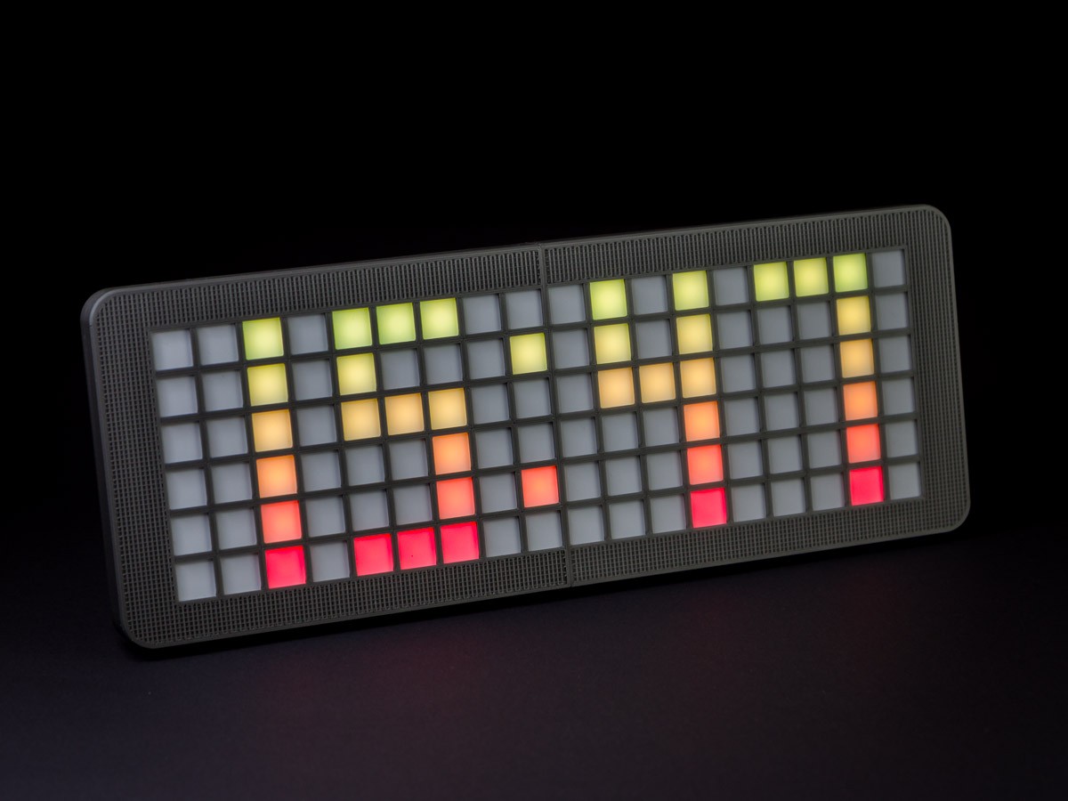
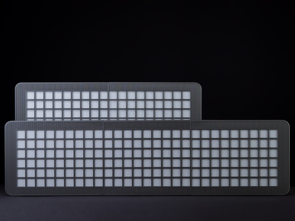
Grid Clock v2 (18x6 and 27x6 pixels)
1. Requirements
To build the grid with 108 leds/2 modules you will need:
Printed parts:
- 2x GCv2_Grid_v1.STL
- 2x GCv2_Grid_Base_v1.STL
- 2x GCv2_Front_v1.STL
- 1x GCv2_Elec_Case_v1.STL
- 1x GCv2_Feet_v1.STL
- 2x GCv2_Cable-Cover_v1.STL
Electronics / Other:
- 1x Arduino (Nano or Pro Mini, case fits both)
(Note: Pro Mini 5V, not 3.3V. ATmega328P, 168P only have 1k SRAM)
- 108x WS2812(B) LEDs (60 leds/m)
- 1x resistor (300-500 ohms, I'm using 330)
- 1x RTC module (DS3231)
- 2x push buttons (6mm x 6mm)
- 1 USB wire to connect the clock/grid later to a power source
(Because of voltage drop I don't recommend wires longer than 2m - 3m max.)
- 10x M3 screws, length anywhere between 7mm - 11mm (I've used m3x10 completely)
- Diffusive material
(copy paper, inkjet film, whatever. Size is 155mm x 107mm per front part)
If you'd like to build the 162 leds/3 modules version from the pictures, you'll need additionally:
Printed parts:
- 1x GCv2_Grid_v1.STL
- 1x GCv2_Grid_Base_v1.STL
- 1x GCv2_Front_XT_v1.STL
- 1x GCv2_XT-Connector_v1.STL
Electronics / Other:
- 54x WS2812(B) LEDs (60 leds/m)
- 4x M3 screws, length anywhere between 7mm - 11mm
Other requirements:
- Working Arduino IDE including the used libraries
- Basic knowledge of what you're doing...
Notes:
Strip cutouts in the base parts are 12.25mm wide. So other strips like APA102 should be usable as long as strip thickness between leds is about 1mm max. IP67/IP65 coated/tubed strips won't work, they're 3mm-4mm thick.
This thing is meant for people who played around a bit with a few WS2812 leds to gather some experience and who are now looking for an easy way to get a working grid. If you're totally new to this you might want to take a look at Adafruits Uberguide or other similar stuff (FastLED user groups) first.
Because of that I won't go into details about power usage/selecting the right wire gauges and so on. If you're going to use the grid for one of your own projects you should know about these things (like about different voltage levels on a esp8266 and the complications that may arise from this). Or why you should keep the power wire short (voltage drop).
The provided sketch is limited to 5V/750mA. Regarding of the diffusive material you chose you might want to raise this. Paper blocks way more light than inkjet film for example. Using AWG24/AWG22 (0.21mm² - 0.33mm²) personally I wouldn't go over 2A - 3A and consider adding one or two capacitors to the strip/arduino.
2. Print Settings
Walls are multiples of 0.6mm. Use an extrusion width of 0.6mm to print these parts, otherwise you'll get much weaker parts and almost double the print times (nozzle diameter != extrusion width!).
Use 2 shells/perimeters so 2.4mm thick walls will get printed without the need for infill.
At 60mm/s - 65mm/s (0.25mm layer height) none of the bigger parts (front, electronics case) should take longer than 60-90 minutes. The other parts (grid, base, feet) take somewhere about 20-40 minutes.
The grid itself can also be printed in vase mode. I've tried to reduce the amount of retractions as far as possible, so this is a very easy print. Unless you suffer from bad 1st layer adhesion, but I suggest getting problems fixed before starting a project... ;)
How to reduce print time from 7+ hours to under 60 minutes for the grid in Cura can be seen in
this video here.
3. Building the Grid
The STLs include smaller parts. The front includes 1 little clamp to connect front parts together (so you get 2 when printing 2 front parts). The front_xt part has 2 clamps within that you'll need.
Remember: Pictures can be opened in a new tab for full resolution!
Adding a 3rd (XT) module in the center should be self explainatory, so this documentation shows building the grid with 2 modules.
Let's break down the process of building this thing into three parts:
A: The LED grid, B: Front/Main Assembly, C: Electronics
A: The LED grid
- Put base parts next to each other as close as possible
- Glue in the led strips, starting with data in on the lower left corner
This will later be X/Y 0,0 - it is extremely important to start there for the sketches to work!
- Connect strips to a horizontal zig zag
- Connect power wire/USB wire to led strip (top left)
- Connect wires for Arduino to bottom left corner (data in, +5v, gnd)
Keep the resistor close to the led strip on the data line here
- Put grids on bases
They don't need to clip together strongly, just to hold everything in place
while mounting the grid inside the front parts later
Steps A1 - A6, the LED Grid.
Sometimes people get confused by how the data flows from start to end when cutting a led strip like this. In the end it's all the same, we just insert some wires at certain points to be able to mount the strip in this way.
Think of it like cars in a traffic jam on a long road (strip) vs. people standing in a line in a theme park (zig zag). Lots of people all going into the same direction, it just looks a bit different...
This should explain it pretty clearly:
Horizontal Zig Zag: First LED at bottom left corner, last one at top left corner.
At the end of steps A1-A6 you should have something like this:
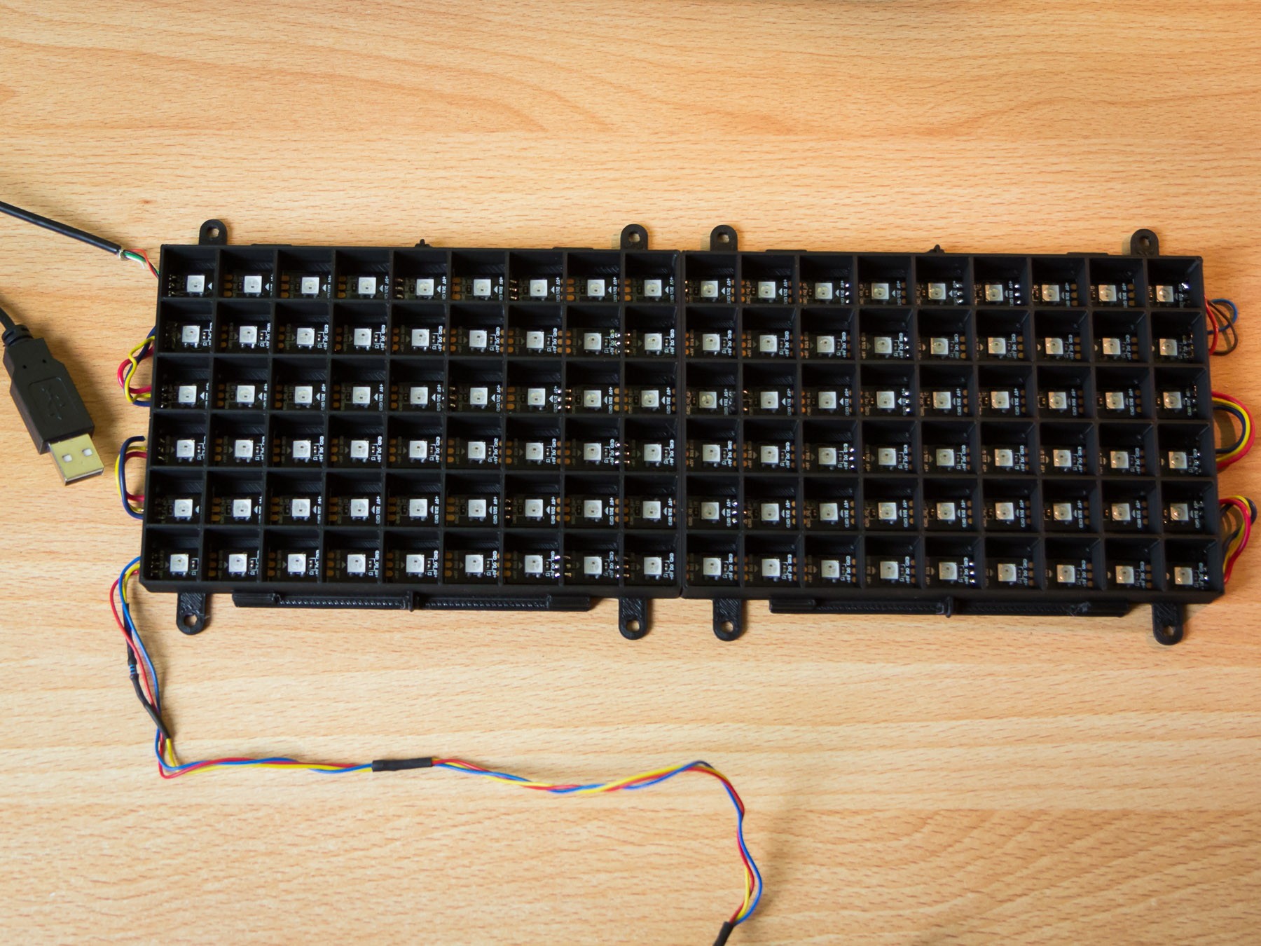
A6 - Grid finished. Data In/+5V/GND to Arduino on the bottom left, USB power top left.
B: Front/Main Assembly
- Connect front parts using the little clamps
- Put diffusive material (paper, inkjet film, ...) in the front parts
- Flip grid/base parts and put them inside the front parts
- Put on Electronics case, cable covers and feet
- Put in all screws except the two for the electronics case cover
This is to keep everything in place while doing the rest. If you don't fix everything now you
might move the diffusive material accidentally.
- This is a good point to put some shrink tubing over the wires coming from the grid to the Arduino
- I recommend routing the USB wire around the pole as some kind of strain relief
Steps B1 - B7, Front/Main Assembly
While putting everything together you should take care of the alignment of the grid inside the front parts. Data In/Power on the right side, buttons pointing upwards. Miss this one and you end up with Data In on the top right corner and mirrored digits... ;)
B4, Watch the alignment of the parts while putting everything together!
At the end of steps B1-B7 this is what it should look like:
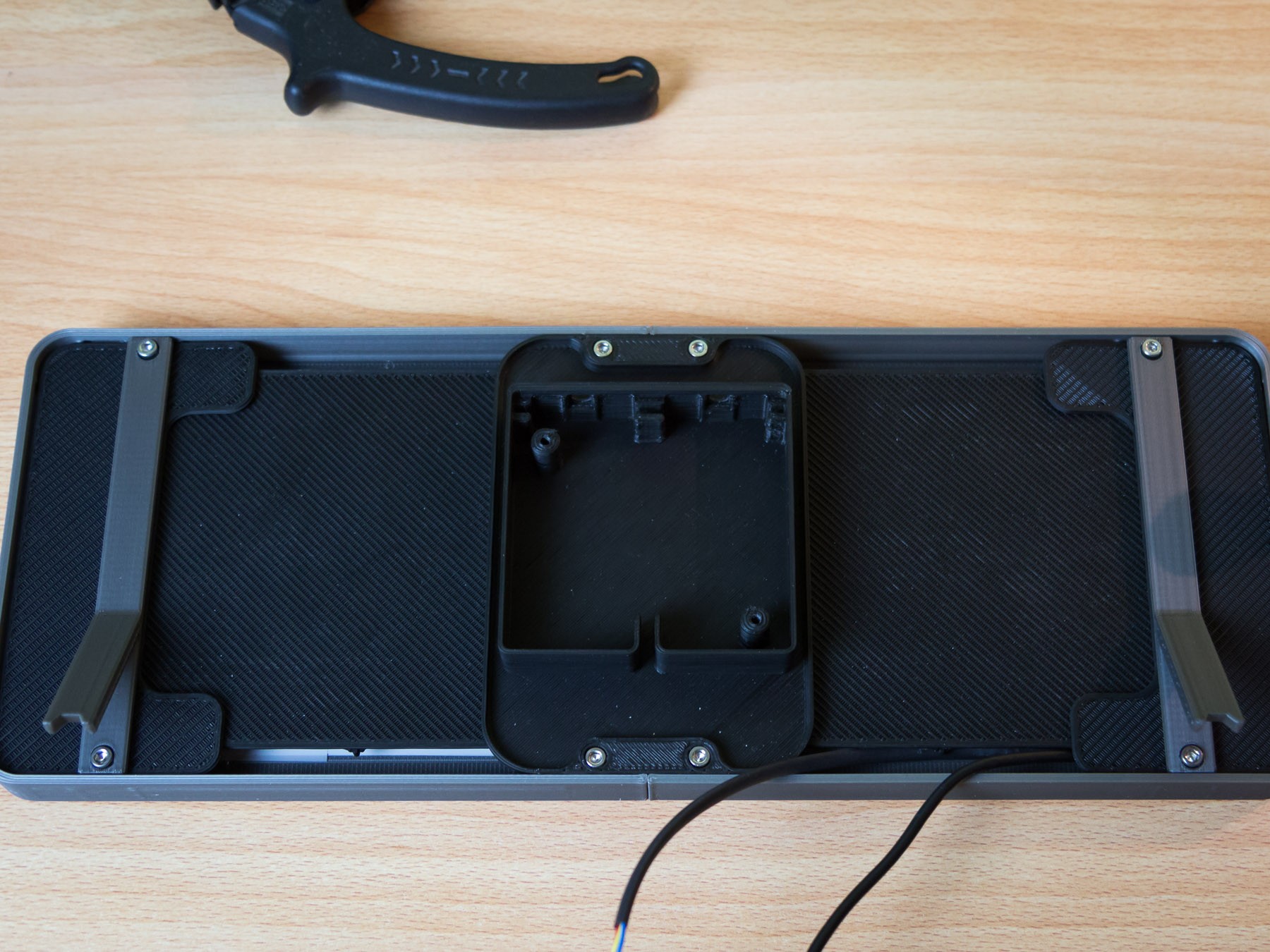
B6, Parts mounted so far, only electronics left.
B7, USB wire routed around pole to avoid accidentally ripping it right off of the grid.
C: Electronics
- Connect two buttons to Arduino - D3 (blue), D4 (purple), GND
- Connect LED strip to Arduino - DataIn (yellow), +5V, GND
When doing this I suggest adding 2 wires to +5V and GND on the Arduino which
will then be used to power the RTC.
- Connect RTC to Arduino - SDA / A4 (white), SCL / A5 (gray), +5V, GND
- Upload sketch to Arduino
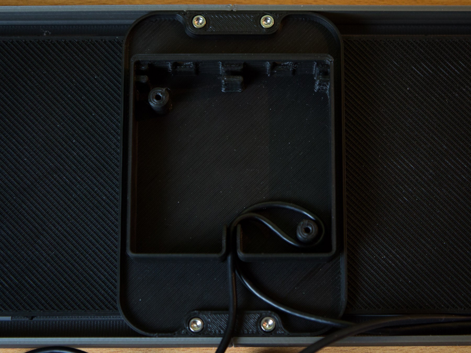
- Put buttons and electronics into the case
- Put cover and screws on electronics case
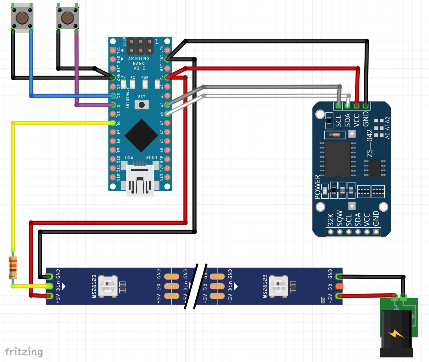
Schematics
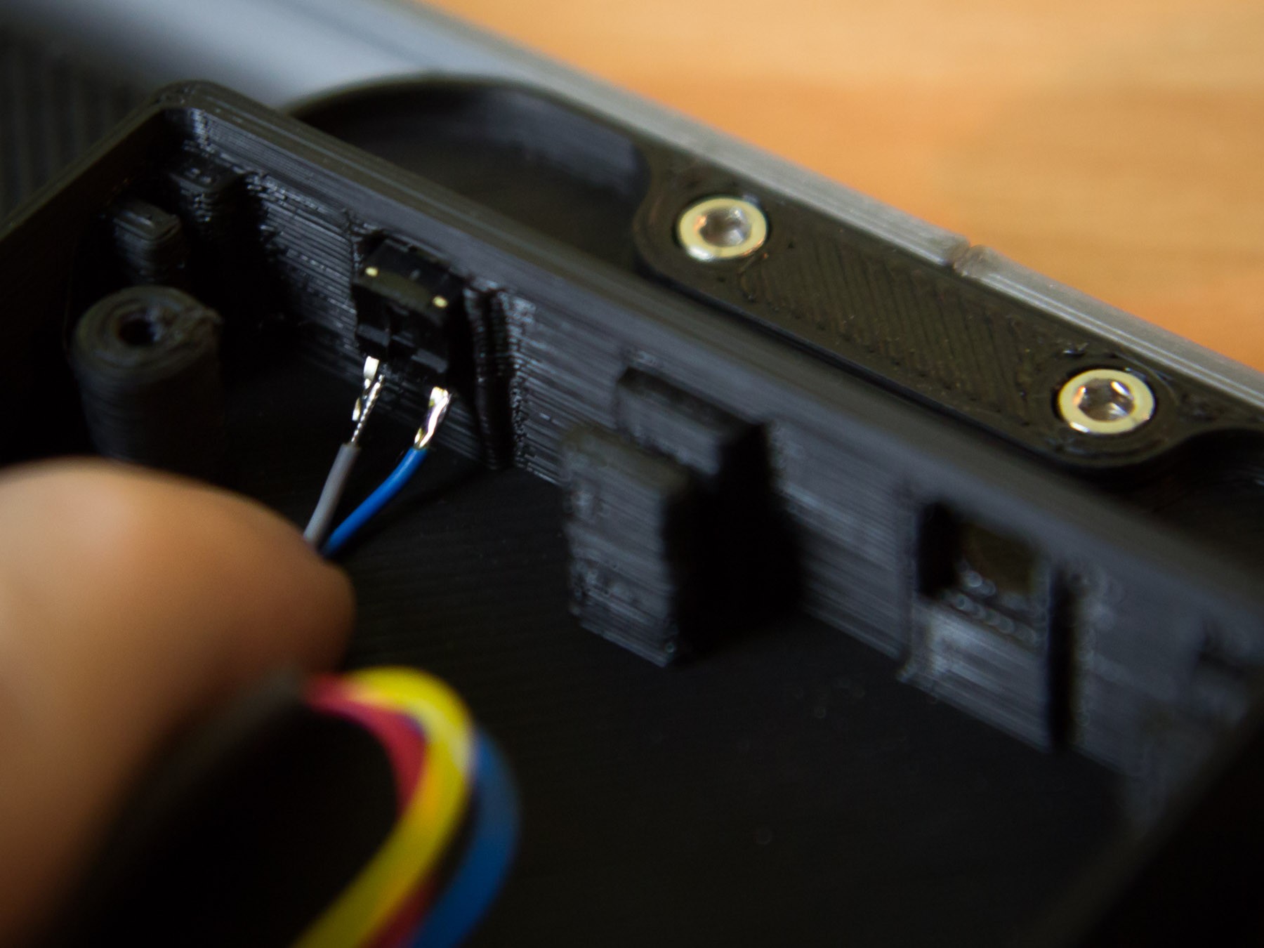
C5, Hold buttons in place...
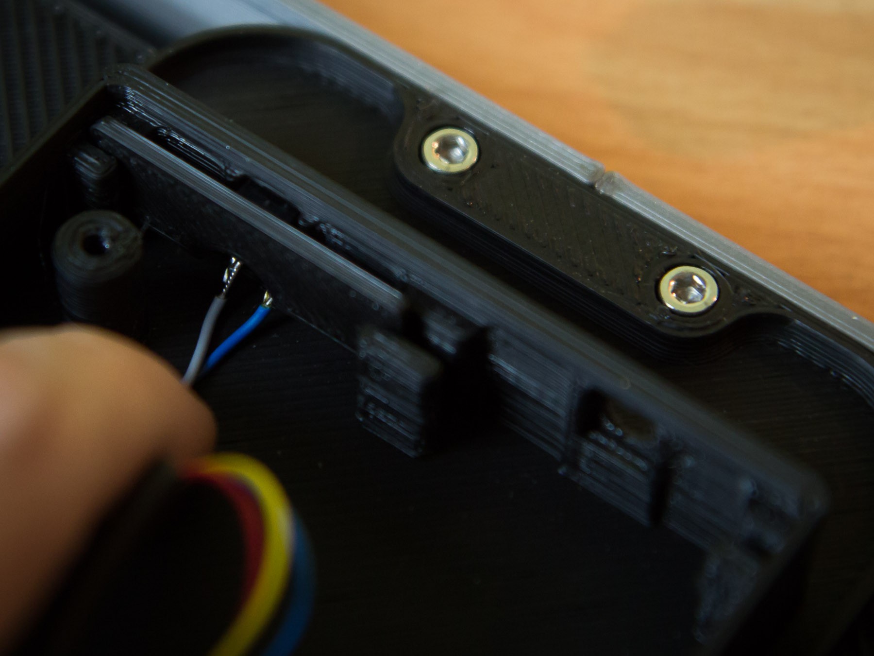
...and fix them by sliding in the little bars.
DONE!